OBD is a diagnostic interface a found on many build in 1996 or later. A description of the OBD protocol can be found below.
RS-232 Serial Cable
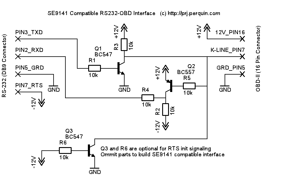
The interface depicted below can be used build a serial cable to connect the serial port of the computer to the 16-pin OBD-II connecter found in many cars build in 1996 or later. This interface only supports the ISO 9141-2 / ISO 14230-2 K-line tranfer mode. If in your ODB connecter pin 7 (K-Line) is present and pin 15 (L-Line) is missing then this interface will most likely work for your vehicle.
The interface has been tested to work with GPL Linux scantool program freediag. A pre-compiled version can be downloaded here.


OBD-II 16 Pin Connector
Alternative ISO interface design: Opto-Coupler Schematic PDF | Jeff Noxon Website
OBD-Microcontroller Interface
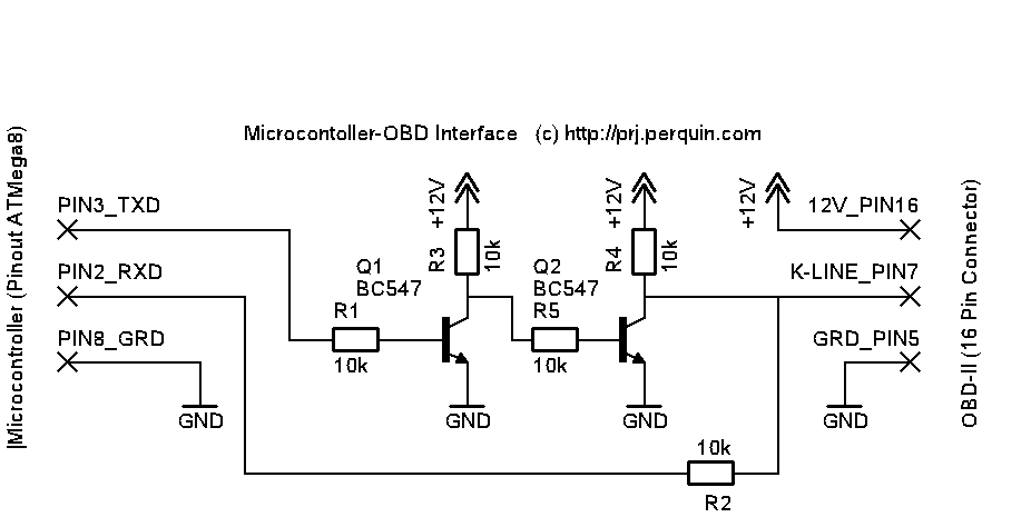
This interface can be used to connect a microcontroller (AVR ATMega8 for example) to the OBD connecter in your car.

OBD-II ISO 14230-2 Protocol Specification
This document describes the OBD-II ISO 14230-2 serial interface protocol. It has been compiled from various public internet sources. I have been successful building an ODB interface with this information, but no guarantee can be given that this information is correct. Use at your own risk.Timing
(in ms) 0-20 Inter byte timing in ECU response 25-50 Time between end of tester request and start of ECU response or between ECU responses 25-5000 Extended mode for "rspPending" 55-5000 Time between end of ECU response and start of new tester request, or time between end of tester request and start of new request if ECU doesn't respond */ 5-20 Inter byte time in tester requestInitialization
Fastinit: _________ _____ ____ ____ \_____/ \/\/\/\/ \/\/\/\/ 300ms 25ms 25ms packet response 1) Wait for 300ms with K line high. 2) Pull K line low for 25 +/- 1 ms 3) Let K line rise high and wait 25ms 4) init serial connection to 10400 baud, 8N1, 1=0Volt 0=12Volt, least significant bit first 5) send package c1 33 f1 81 66 33=dest, f1=our tester id, 81=start comms 6) wait for response 83 f1 01 c1 e9 8f ae 01=physical address, c1=response ok (7f=fail), e9=kb1, 8f=kb2 Slowinit: _________ S ___ 2 3 ___ 6 7 ___ ____ ____ \_/0 1\___/4 5\___/P \/\/\/\/ \/\/\/\/ 300ms 200 400 400 400 400 250 packet response 1) Wait for 300ms with K line high. 2) send a byte 33 hex at 5 baud. 200ms per bit startbit: 200ms low databit0,1: 400ms high databit2,3: 400ms low databit4,5: 400ms high databit6,7: 400ms low stopbit+pause: 250ms high 4) init serial connection to 10400 baud, 8N1, 1=0Volt 0=12Volt, least significant bit first 5) send package c1 33 f1 81 66 33=dest, f1=our tester id, 81=start comms 6) wait for response 83 f1 01 c1 e9 8f ae 01=physical address, c1=response ok (7f=fail), e9=kb1, 8f=kb2Packets
Send command packet: header: [c0+cmdlen] [destination=33] [source=f1] data: [cmd0] [cmd1] ... [cmd(cmdlen-1)] checksum: [sum(header)+sum(data)] cmd0 = service ID cmd1 = PID Received response packet on success: header: [80+datalen] [destination=f1] [source=01] data: [40+cmd0] [cmd1] ... [cmd(cmdlen-1)] [result0] [result1] ... [result(datalen-cmdlen-1)] checksum: [sum(header)+sum(data)] Received response packet on failure: header: [80+datalen] [destination=f1] [source=01] data: [errorcode=7f] [cmd0] [Response Failure Code, see below] checksum: [sum(header)+sum(data)] Multibyte data is sent high byte first.Tester Commands
request and response packet diagram format: cmd0 cmd1 ... -> result0 result1 ... comment Note: only the data of the request and only the result of the response are show. yy 00 -> xx xx xx xx bitmask of capabilities for mode yy, bit7 represents pid 1, bit6 pid 2, etc, if data4:bit0 is set then pid 20 contains capabilities for pid 21-40 00-0F: SAE J1979 Diagnostic Test Modes 01 00 -> xx xx xx xx capabilites 01 01 -> [b7: MIL light, b0-6: dtc count] [b4-7: readiness] [b5: o2monitoring] [b0-7: readiness] 01 03 -> xx xx Fuel System Status bitmap b0:Open, b1:Closed, b2:Open-Driving, b3:Open-Fault, b4:Closed-Fault 01 04 -> xx Calculated Load Value % x*100.0/255 01 05 -> xx Engine Coolant Temperature C x-40 01 06 -> xx Short term fuel trim Bank 1 % x*(100.0/128)-100 01 07 -> xx Long term fuel trim Bank 1 % x*(100.0/128)-100 01 08 -> Short term fuel trim Bank 2 % x*(100.0/128)-100 01 09 -> Long term fuel trim Bank 2 % x*(100.0/128)-100 01 0a -> Fuel Pressure kPaG x*3 01 0b -> xx Intake Manifold Pressure kPaA x 01 0c -> xx xx Engine RPM RPM x*0.25 01 0d -> xx Vehicle Speed km/h x 01 0e -> xx Ignition timing advance Cyl #1 deg X*0.5-64 01 0f -> xx Intake Air Temperature C X-40 01 10 -> xx xx Air Flow Rate gm/s X*0.01 01 11 -> xx Absolute Throttle Position % X*(100.0/255) 01 12 -> xx Commanded secondary air status 01 13 -> xx Oxygen sensor locations bitmap b0=sensor1, b1=sensor2, ..., b7=sensor8 01 14 -> xx yy Bank 1 Sensor 1 Voltage/Trim V, % x*0.005, if y!=ff then y*(100.0/128)-100) 01 15 -> xx yy Bank 1 Sensor 2 Voltage/Trim V, % x*0.005, if y!=ff then y*(100.0/128)-100) 01 16 -> Bank 1 Sensor 3 Voltage/Trim V, % x*0.005, if y!=ff then y*(100.0/128)-100) 01 17 -> Bank 1 Sensor 4 Voltage/Trim V, % x*0.005, if y!=ff then y*(100.0/128)-100) 01 18 -> Bank 2 Sensor 1 Voltage/Trim V, % x*0.005, if y!=ff then y*(100.0/128)-100) 01 19 -> Bank 2 Sensor 2 Voltage/Trim V, % x*0.005, if y!=ff then y*(100.0/128)-100) 01 1a -> Bank 2 Sensor 3 Voltage/Trim V, % x*0.005, if y!=ff then y*(100.0/128)-100) 01 1b -> Bank 2 Sensor 4 Voltage/Trim V, % x*0.005, if y!=ff then y*(100.0/128)-100) 01 1c -> xx Auxiliary Input Status bitmap b0:PTO Active 01 20 -> xx xx xx xx capabilities 01 21 -> xx xx 02 00 00 -> xx xx xx xx capabilites SMART: 2 3 4 5 6 7 b c d 02 02 00 -> [dtc1h] [dtc1l] DTC that caused freezeframe 03 -> [dtc1h] [dtc1l] 00 00 00 00 05 00 00 -> xx xx xx xx capabilites 06 00 -> xx xx xx xx capabilites 06 yy -> [max=01,min=81] [valH] [valL] [limitH] [limitL] example 01 00 23 01 2c is value 23 (=35 dec) with limit maximum 12c (=300 dec) 06 01 -> xx xx xx xx xx ncms 06 02 -> xx xx xx xx xx ncms 06 09 -> 01 xx xx xx xx -> 81 xx xx xx xx ncms 07 -> 00 00 00 00 00 00 cms 08 00 00 00 00 00 00 -> xx xx xx xx capabilites SMART: none 09 00 -> 01 30 00 00 00 capabilites 5 bytes??? 10 Start Diagnostic Session 11 ECU Reset 12 Read Freeze Frame Data 13 Read Diagnostic Trouble Codes 14 Clear Diagnostic Information 17 Read Status Of Diagnostic Trouble Codes 18 Read Diagnostic Trouble Codes By Status 1A Read Ecu Id 20 Stop Diagnostic Session 21 Read Data By Local Id 22 Read Data By Common Id 23 Read Memory By Address 25 Stop Repeated Data Transmission 26 Set Data Rates 27 Security Access 2C Dynamically Define Local Id 2E Write Data By Common Id 2F Input Output Control By Common Id 30 Input Output Control By Local Id 31 Start Routine By Local ID 32 Stop Routine By Local ID 33 Request Routine Results By Local Id 34 Request Download 35 Request Upload 36 Transfer data 37 Request transfer exit 38 Start Routine By Address 39 Stop Routine By Address 3A Request Routine Results By Address 3B Write Data By Local Id 3D Write Memory By Address 3E Tester Present 81 -> xx xx Start Communication 82 Stop Communication 83 Access Timing Parameters 85 Start Programming ModeResponse Failure Codes
10 General Reject 11 Service Not Supported 12 Sub Function Not Supported - Invalid Format 21 Busy - repeat Request 22 Conditions Not Correct Or Request Sequence Error 23 Routine Not Complete Or Service In Progress 31 Request Out Of Range 33 Security Access Denied - security Access Requested 35 Invalid Key 36 Exceed Number Of Attempts 37 Required Time Delay Not Expired 40 Download Not Accepted 41 Improper Download Type 42 Can Not Download To Specified Address 43 Can Not Download Number Of Bytes Requested 50 Upload Not Accepted 51 Improper Upload Type 52 Can Not Upload From Specified Address 53 Can Not Upload Number Of Bytes Requested 71 Transfer Suspended 72 Transfer Aborted 74 Illegal Address In Block Transfer 75 Illegal Byte Count In Block Transfer 76 Illegal Block Trasnfer Type 77 Block Transfer Data Checksum Error 78 Request Correcty Rcvd - Rsp Pending 79 Incorrect Byte Count During Block Transfer 80 Service Not Supported In Active Diagnostic Mode C1 Start Comms +ve response C2 Stop Comms +ve response C3 Access Timing Params +ve response 81-8F Reserved 90-F9 Vehicle manufacturer specific FA-FE System supplier specific FF Reserved by documentSample scan obtained of a SMART FOR TWO car
--wakeup 81 -> e9 8f --get capabilities 01 00 -> b2 3f f8 11 capabilities service 1: 1 3 4 5 6 7 b v d e f 10 11 12 13 14 15 1c 20 01 20 -> 80 00 00 00 capabilities service 1: 21 02 00 00 -> 7e 38 00 00 capabilities service 2: 2 3 4 5 6 7 b c d 05 00 00 -> 7f 05 11 capabilities service 5: none 06 00 -> ff c0 80 00 capabilities service 6: 1 2 3 4 5 6 7 8 9 a 11 08 00 00 00 00 00 00 -> 7f 08 11 capabilities service 8: none 09 00 -> 01 30 00 00 00 ???? expected 4 byte response... --get status 01 01 -> 01 07 69 00 MIL light off, 1 dtc, ready, no 02monotoring --get dtc's 03 -> 07 02 00 00 00 00 dtc P0702 --scan sensors 01 03 01 04 01 05 -> 3a engine coolant temp = 18C (3a=58 dec - 40 dec) 01 06 01 07 01 0b 01 0c 01 0d 01 0e 01 0f 01 10 01 11 01 12 01 13 -> 03 2 sensors 01 14 01 15 01 1c 01 20 -> 80 00 00 00 (always same: capabilities 21-40) 01 21 -> 00 37