This is an interrupt driven DALI interface for Arduino. It can be used as a master or slave in a DALI Lighting system, for example as a dimmer for LED Panels.

Download the DALI library

The library is capable of running multiple DALI interfaces simultaneously. The example program demonstrates with a DALI Master (interface dali1) sending commands received by the DALI Slave (interface dali2) on a single Arduino.


/*###########################################################################
DALI Interface Demo

On the Arduino connect pin18 and pin19 together

Dali interface1 transmit on pin18, interface2 receives on pin19

----------------------------------------------------------------------------
Changelog:
2014-02-07 Created & tested on ATMega328 @ 16Mhz
----------------------------------------------------------------------------
        pq_Dali_Demo.ino

        This program is free software: you can redistribute it and/or modify
        it under the terms of the GNU General Public License as published by
        the Free Software Foundation, either version 3 of the License, or
        (at your option) any later version.

        This program is distributed in the hope that it will be useful,
        but WITHOUT ANY WARRANTY; without even the implied warranty of
        MERCHANTABILITY or FITNESS FOR A PARTICULAR PURPOSE.  See the
        GNU General Public License for more details.

        You should have received a copy of the GNU General Public License
        along with this program.  If not, see <http://www.gnu.org/licenses/>.

        see http://blog.perquin.com for latest, bugs and info
###########################################################################*/

#include "pq_Dali.h"

//create the DALI interfaces
Dali dali1; 
Dali dali2; 

//callback to handle received data on dali2 interface
void dali2_receiver(Dali *d, uint8_t *data, uint8_t len) {
  Serial.print("RX");
  if(len>=2) Serial.println((int)(data[0]<<8) + data[1]); else  Serial.println((int)data[0]);
}

void setup() {
  Serial.begin(115200);
  Serial.println("DALI Master/Slave Demo");

  //start the DALI interfaces
  //arguments: tx_pin, rx_pin (negative values disable transmitter / receiver)
  dali1.begin(18,-3); 
  dali2.begin(-2,19);

  //attach a received data handler
  dali2.EventHandlerReceivedData = dali2_receiver;
}

uint16_t i=0;

void loop() {
  Serial.print("tx");
  Serial.println(i);
  dali1.sendwait_int(i);
  //delay(200);
  i+=1;
}

Klassische Auto-Race Spiel auf einem Deskjet 520.

AVI video (1.5MB) von einen Race.

Klick auf ein Bild um das 4-Megapixel Orginalbild anzuzeigen (1.5MB)


Das Parkur-Papier (in diese Fall zwei A4 lang) wird geladen durch die Joystick nach vorne zu drucken.


Wenn der Parkur geladen ist zeigt das LCD “Positionieren”, jetzt kann der Deskjet-Pilot sein Bolide im Position bringen mit Joystick links/rechts. Der Race startet sobald der Joystick nach forne bewegt wird. Solange das Auto auf dem Parkur ist sind hohe Geschwindigkeiten moechlich. Sobald jedoch das Auto von Parkur abkommt, verringert sich die Hoechstgeschwindigkeit. Ziel ist jetzt den Parkur so schnell wie moeglich zu absolvieren.
Es gibt auch ein AVI video (1.5MB) von einen Race.


Beim erreichen des Ziels schaltet der Deskjet ab, und…


Die Rennzeit wird im Display angezeigt.

Bauanleitung


Oeffne ein Deskjet der 500er Reihe (hier 520).


Auf dem Haupplatine wirden folgende Leiterbanen abgetrennt und umgeleitet zum Microkontroller auf dem Breadboard:
- links-oben: Ground Leitung und +5Volt Leitung.
- links-mitte: 4x Stepper Motor Controller Leitungen
- links-unter: 2x Druckkopf Positions Encoder, und 1x “Papier-Aus” Sensor.
- rechts-oben: 3x Druckkopf DC Motor Controller Leitungen.


Der Papierfeederteil wird wieder installiert, wobei es wichtig ist das Druckkopfkabel (weisse Flachkabel unter-mitte) wieder anzuschliesen fuer die Druckkopf Position und “Papier-Aus” Sensoren. Auch werden zwei Holzkloeze installiert die die Bewegungsfreiheit des Druckkopfes auf die Papierbreite beschraenken.


Aus einem Phototransistor und Infrarot LED wird der (licht-dunkel) Parkursensor gebaut. Ein kleines Stueck Plexiglass haelt den Sensor auf ein4er fixen Hoehe ueber dem Papier, so kann der Sensor Ausgangswert kalibriert werden.


Im oberen Gehaeuse-Teil sind die Anschluesse fuer dem Reset-Knopf und Power-On LED.


Die Druckkopfabdeckung vor dem Ausschnitt.


Der fertige Deskjet Racer!

Software

Das austausch Gehirn des Deskjets ist ein ATMega8 Microkontroller (Einzelhandelspreis Euro 3.50). Mit einem, im gcc programmiertem, Programm ist es moeglich Paperfeed Stepper motor und Druckerkopf DC Motor mit variabeler Geschwindigkeit zu steuern. Im Hauptloop des Programms wird die X und Y Position des Joysticks und der Photosensorwert ausgewertet und demensprechend wird die Geschwindigkeit der Motoren angepasst.

Microkontrollers Pin Benutzung:

Pin:Pinname Funktion
 1:RESET programmmer
 2:RXD   serial port
 3:TXD   serial port
 4:INT0  x position phase0
 5:INT1  paperout
 6:PD4   stepper phase0
 7:VCC   VCC
 8:GRD   GRD
 9:PB6   dc motor1
10:PB7   dc motor2
11:PD5   stepper phase1
12:PD6   stepper phase2
13:PD7   stepper phase3
14:PB0   x position phase1
 
15:OC1A  dc motor enable
16:PB2   lcd D4
17:PB3   lcd D5 / MOSI  programmer
18:PB4   lcd D6 / MISO  programmer
19:PB5   lcd D7 / SCK   programmer
20:AVCC  N/C
21:AREF  VCC
22:GRD   GRD
23:ADC0  joystick x
24:ADC1  joystick y
25:ADC2  light sensor
26:
27:PC4   lcd E
28:PC5   lcd RS

Microkontroller Resources:
- Interer Kalibrierte RC-Oscillator auf 8MHz.
- Drei ADC Kanaele: zwei fuer die Joystick-Position und eine fuer den Photosensor (schwarz-weiss).
- 8-Bit Timer2 wird benutzt zum Geschwindigkeit-Kontrolle des Paperfeed Stepper-Motor.
- 8-Bit Timer0 wird benutzt als Zeitbasis mit 4kHs Resolution.
- Interrupt0 wird benutzt zum Auswerten des Druckerkopfes Positions Enkoder.

Play poker over TCP internet connection

Download: PokerClient and PokerServer | VB6 Source Code

Description

For a quick demo on a single computer: run the test.bat file. This will
open the poker server and two clients. The clients will automatically
connect to the PokerServer running on the computer, login, and start a
game. Click on the cards to change them, then press the Done button.
Now place your bets.

To run over a network (or internet), run the PokerServer program on a
computer and make sure the filewall is configured to accept incoming
connection to port 9596.

On a different computer run PokerClient and enter the IP address (or
hostname) of the PokerServer computer when prompted. Select “New Game”
from the Game menu.

Run the PokerClient on up to 5 additional computers and select “Join
Game” from the menu and select game number 1.

Have Fun!

Screenshots


Poker Client Player 1


Poker Client Player 2, with Client-Server communication visible


Poker Server

TODO

  • Persistant useraccounts
  • Better “Join Game” dialog, showing available games
  • Better handling of lost connections / reconnects.

    License

    This program is free software; you can redistribute it and/or
    modify it under the terms of the GNU General Public License
    as published by the Free Software Foundation; either version 2
    of the License, or (at your option) any later version.

    This program is distributed in the hope that it will be useful,
    but WITHOUT ANY WARRANTY; without even the implied warranty of
    MERCHANTABILITY or FITNESS FOR A PARTICULAR PURPOSE. See the
    GNU General Public License for more details.

    You should have received a copy of the GNU General Public License
    along with this program; if not, write to the Free Software
    Foundation, Inc., 59 Temple Place – Suite 330, Boston, MA 02111-1307, USA.

  • With this software you can simulate in 3D a mobile robot in a maze. Included are the maze layout and robot used in the c’t robot contest. Also included is a full installer/uninstaller.

    Download Robot Simulator (400kb)
    To install, run the downloaded file. To unistall, select uninstall from the Start menu.

    Screenshots


    Robot Simulator Uses’ Manual

    Manual updated to build 011023:003

    Robot Simulator Program Keys

    GENERAL

    ESC: Quit
    F12: Toggle full screen/window
    R: Reload scene configuration

    OBJECT MANIPULATION
    1-9,0: Select object, object 1 is the robot.
    Left/right arrow: Turn object left/right
    Up/down arrow: Move object forward/backward

    CAMERA CONTROL

    F1-F6: Select camera (keep pressed until view changes). Cameras can at a fixed position or can be mounted on a object.
    A/D: Turn camera left/right.
    W/S: Move camera forward/backward.
    Page up/down: Move camera up/down.
    Home/End: Turn camera up/down.

    Scene Configuration

    The scene configuration is stored in the text file config.txt in the working directory. The following commands can be used in the configuration file. A command is aways on a separate line and starts with the command name, followed by the command arguments. Units are in meters. Blank lines are ignored. Any characters appearing after the hash (#) character are considered comments.

    Configuration Commands

    Camera camno posx posy posz rotz lookup objno Define a camera at position and rotation. If objno>0 then the camera is bound the object with that objno. Last camera defined is the active camera upon startup.
    ObjectStart objectno Start an object definiton block. Last object defined is the active object upon startup.
    Position posx posy posz Set object positon
    Orientation rotx roty rotz Set object orientation
    Collision limit Turn on collision detection for this object. Limit is the radius within no other object can approach this object.
    PushMatrix Push current transformation matrix on stack
    Translate x y z Translate position
    Rotate deg axisx axisy axisz Rotate along axis
    Color r g b alpha Set color
    DrawBox sizex sizey sizez Draw box at current position
    DrawDisk radius thickness no_segments Draw a disk around the z-axis
    DrawBase width lenght height thickness Draw base plane in coloridx 0, with walls around it.
    DrawWall x1 y1 x2 y2 height thickness Draw a wall.
    PopMatrix Pop transformation matrix from stack
    ObjectEnd End object definiton

    Collision Detection

    The program uses 3D collision detection between objects and walls. Objects are represented for collision detection purposes by a sphere centered at objects Position, with radius set with the Collision command. Collision betweens between objects will move the object collided into in the same amount as the moving object.

    The autonomous robot “Don Quichotte” (Don Quixote in English spelling) was designed to compete in the “c’t magazine cleaning robot contest” held on October 14-19, 2001 on the Systems trade show in München Germany. The idea was to build a versatile robot that is not only capable to solve the tasks defined by this specific contest, but that can be easily reprogrammed for other tasks.

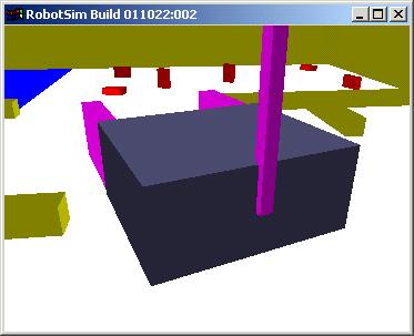
    Robot without front scoop

    Don Quichotte Fact Sheet

    Measurements (lxbxh) 30 x 33 x 18 cm (main unit)
    30 x 22 x 13 cm (Front scoop)
    140 cm (height of camera)
    Wheel diameter 15 cm (main)
    3 cm (castor)
    Weight 9 kg (including 2.5 kg laptop)
    Material Plywood, wood
    Battery 12v 7.2Ah sealed lead-acid
    Operating time before recharge >1.5 hours
    Speed 25 cm/sec (1 km/h)
    Electronics Dell Latitude CPiA Celeron 366/64MB laptop

    Logitech Quickcam Pro3000 USB camera

    IPC@Chip SC12 microcontroller

    L298 dual motor driver

    Robbe S161 RC-Servo

    Two automotive rear view window wiper motors

    Software Laptop: Custom program in C++ (MS-Visual C++), Logitech SDK, Intel Image Processing Library

    Microcontroller: Custom program in C (Borland Turbo C)

    Construction

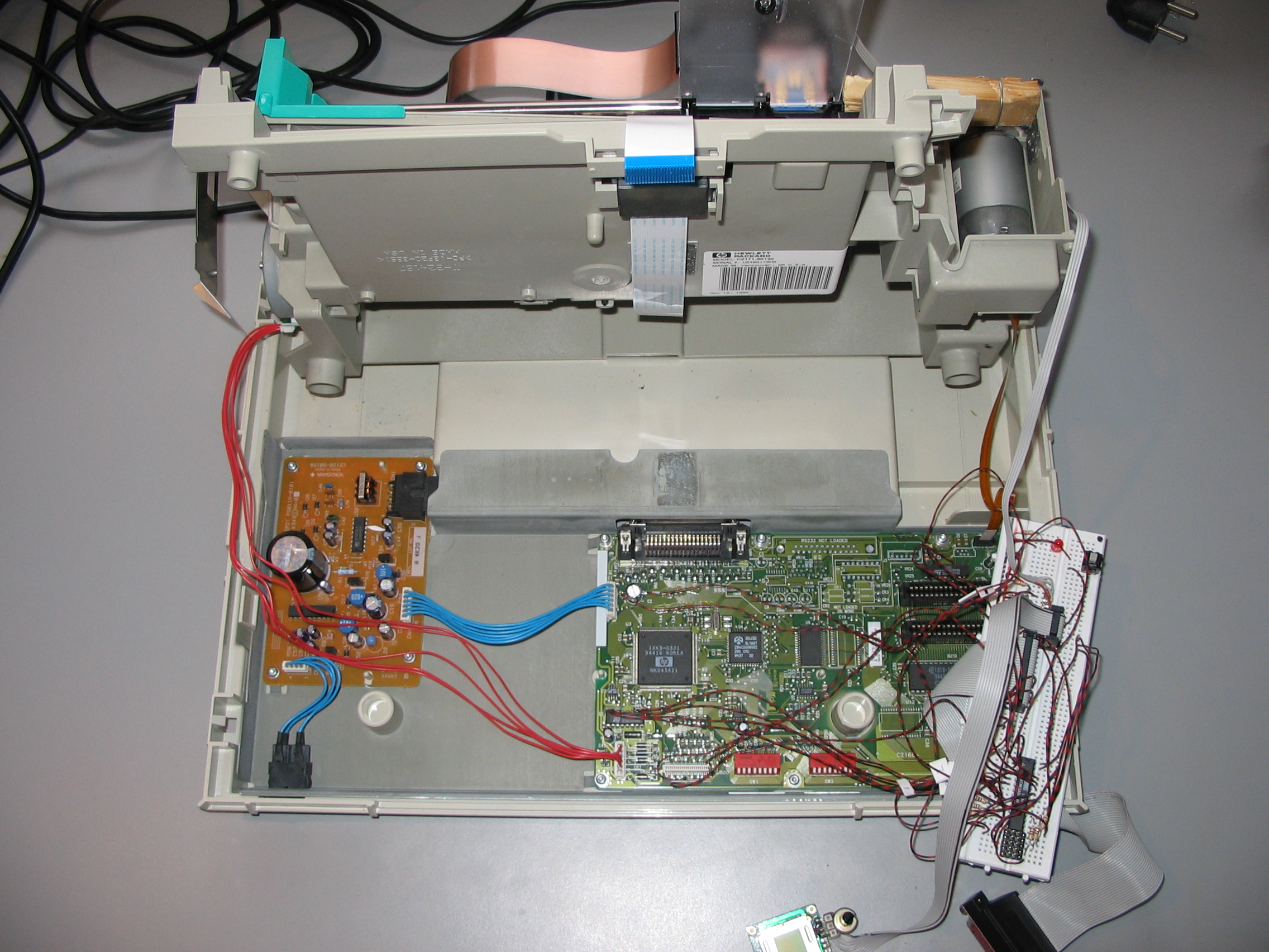
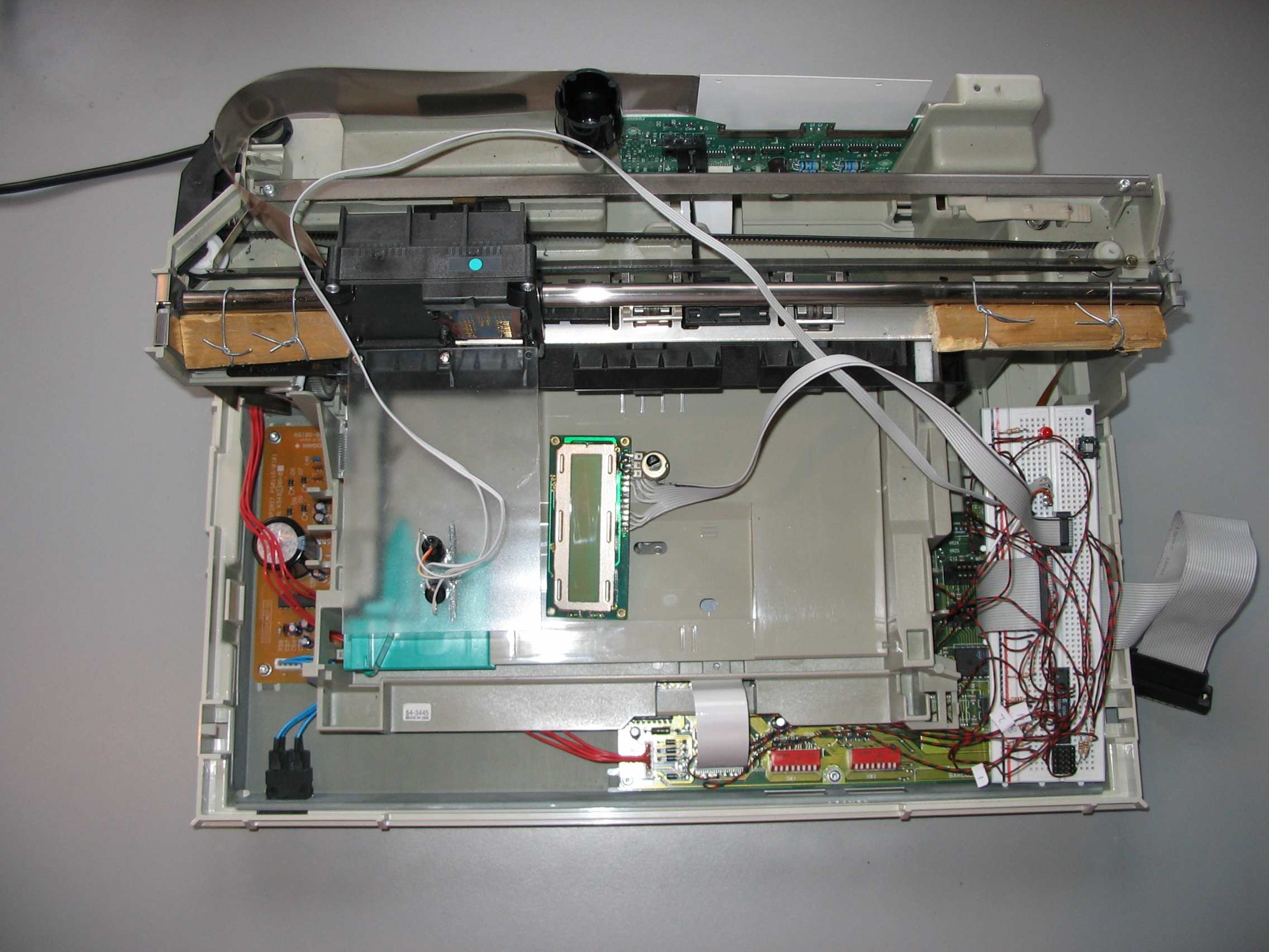
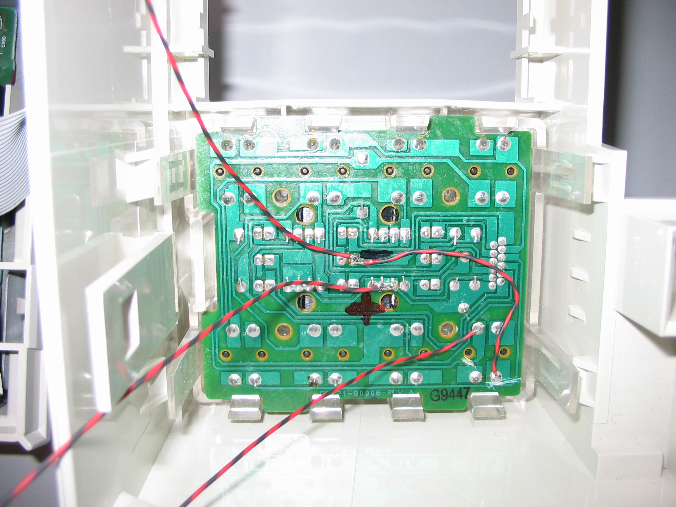
    Don Quichotte is contructed out of plywood and wood. A bumper in front connected to two micro switches senses forward collisions. A scoop made out of cardboard and soft PU foam is mounted to the bumper. Mobility is provided by differential steering on two 12volt automotive rear window wiper motors. The motors are driven by a L298 dual motor driver, which in turn is controlled by the SC12. Power for the motors is provided by a sealed lead accu. A Logitech QuickCam Pro 300 is mounted on the robot with a wooden stick, at about 140cm above ground level. The camera angle can be changed with a RC-servo, controlled by the SC12. A Pentium Celeron 366MHz/64MB laptop is mounted on top of the robot. The laptop is powered by it’s own batteries. The laptop is connected to the SC12 microcontroller by RS-232 at 19200 baud, the bumper sensors are connected via the Parallel port.

    Sensors

    The main sensor is the USB camera mounted on the robot. The camera vision angle is controlled by a convential RC-servo, driven by a SC12 microcontroller. The front scoop is equipped with two micro switches in order to detect collision with non moving items. The state of the micro switches can be read by the laptop via the parallel port. Light items, in the case of the contest the empty cans and cigarette boxes, will not trigger the collision detection sensor. These items will be pushed by the robot to the target area. The wheels have mechanical rotation sensors in order to obtain an approximate position of the robot. The rotation sensor switches 6 times on and off per revolution of a main wheel, output is sent via the parallel port to the laptop.

    The Task

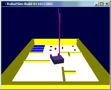
    The robot is placed in an 3 by 2 meter arena. The arena has an uniform white/gray colored underground and is enclosed with yellow walls enclosed. In the arena several yellow walls are placed to resemble an office floor with approximately 5 rooms. In one of the rooms several red colored items (empty beercans and cigarette boxes) are placed. In the same room a square target area is marked with ground and walls colored blue. The task of the robot is to find its way to the room with the items, and then collect these items and drop them in the target area. The minimal opening between the walls is 40cm, the starting position of the robot is diagonally across from the target area.
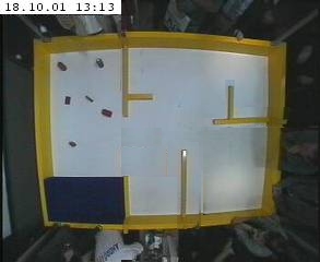

    Robot Arena

    Software

    The robot uses proprietary software on the laptop and microcontroller to process the images from the camera and steer the robot.

    On the laptop a Visual C++ GUI program runs.With the GUI the user can calibrate the camera angle, calibrate the camera setting so that colors are recognized correctly, and start/stop or step the robot program. The program generates debug information on screen for each step in the robot program, including the current state and actions. The image frame feed from the camera is also shown, including three additional images showing raw color filtered images, completely processed images including identified object positions, and image giving information about the last program step.

    Image Processing

    The camera sends image frames to the image processing routine. For the task at hand the robot processes images in three layers: the items to be collected, the target area, and the walls. The processing takes the following steps:

    1. Convertion of RGB image to HSV color space.

    2. Filter out appropriate color, resulting in a binary layer image (zero color not present and 1 color present).

    3. Layer noise filtering

    4. Layer feature enhancement.

    Noise filtering is performed by a single pixel erode operation followed by a single pixel dilate operation. The erode operation sets the output picture to zero if the corresponding input pixel or any of its 9 neighboring pixels is a zero. The dilate operation sets the output pixel to 1 if the corresponding input pixel is 1 or any of 8 neighboring input pixels is 1. The two operations combined have the effect of eliminating small and thin objects, breaking objects at thin points, and generally smoothing the boundaries of larger objects without significantly changing their area.

    Feature enhancement is dependent on the layer involved. For the item layer, containing multiple relatively small objects, no further processing is done. For the target layer, containing a single relatively large object, an 6 pixel dilate operation is followed by a 6 pixel erode. This has the effect of filling small and thin holes in the objects, connecting nearby objects, and generally smoothing the boundaries of objects without significantly changing their area. Walls not noise filtered but are smoothed and connected by a single pixel dilate/erode operation.

    Object Position Estimates

    The enhanced item and target layer information is fed to a object position estimate routine. The routine calculates the positions (in pixel coordinates) of each object in the image.

    The pixel coordinates are then transformed into cm grid coordinates relative to the robot main wheel axis center point. The transformation is depenent on the camera position. The camera has three angle of view position, Down, Near and Far. After calibration of the camera positions, the program is able to calculate the position of objects relative to the robot. The calculated position accuracy is 5 cm or better for the camera Down and Near positions. The width of vision is about 160 cm. The field of vision in forward direction is dependent on the camera position:

    Camera Down: -30 to +70cm (relative to the robot main wheel axis center point),

    Camera Near: +15 to +110cm,

    Camera Far: +60 to 200cm.

    At present no position calculation routine is available for line features (walls). For wall avoidance and following a routine is used that counts the number of ones in a specific subarea of the wall layer.

    Movement

    The robot moves by sending pulses of known length to the two motors. A calibration is made for all eight movement modes in order to be able to translate move and turn commands from cm and degrees to pulse duration in milliseconds. The eight movement modes are: move forward/backward, turn left/right, forward moving left/right turn, backward moving left/right turn. The move command with duration is send by RS-232 from the laptop to the microcontroller. The microcontroller takes care of the exact timing of actual pulses sent to the motors.

    Robot Program

    The actual robot control program is build up out of several sub programs. The sub programs are:

    INIT: Initialization. Run either WALL_FOLLOW or TARGET_FIND.

    WALL_FOLLOW: Follow walls until target area is identified. If target identified, store target position and run TARGET_RETURN.

    TARGET_FIND: Move until a wall is hit or target is identified. If target identified, store target position and run TARGET_RETURN. If wall is hit, turn randomly.

    TARGET_FINDNEAR: Assuming that target is same room. Turn around trying to identify the target, if identified run TARGET_RETURN.

    ITEM_FIND: Assuming just dropped an item. Look around and identify closest item.

    ITEM_GO: Goto identified item. Update target position with each move.

    TARGET_RETURN: Return to memorized target position with item. If target can not be found, run TARGET_FINDNEAR

    ITEM_DROP: Drop item in target area, backup, turn 180 degrees, run ITEM_FIND.

    Each subprogram consists of steps. A step can be a movement, camera repositioning, or a jump to a next program. Between steps the image frame is updated. While a move or camera command is being executed , the robot program is suspended till after the command is completed and a fresh image frame is available.

    © 2018 Tech Toy Hacks Suffusion theme by Sayontan Sinha