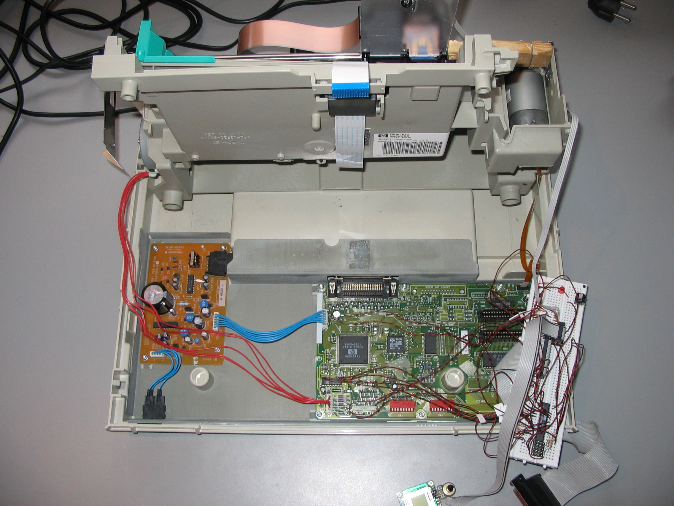
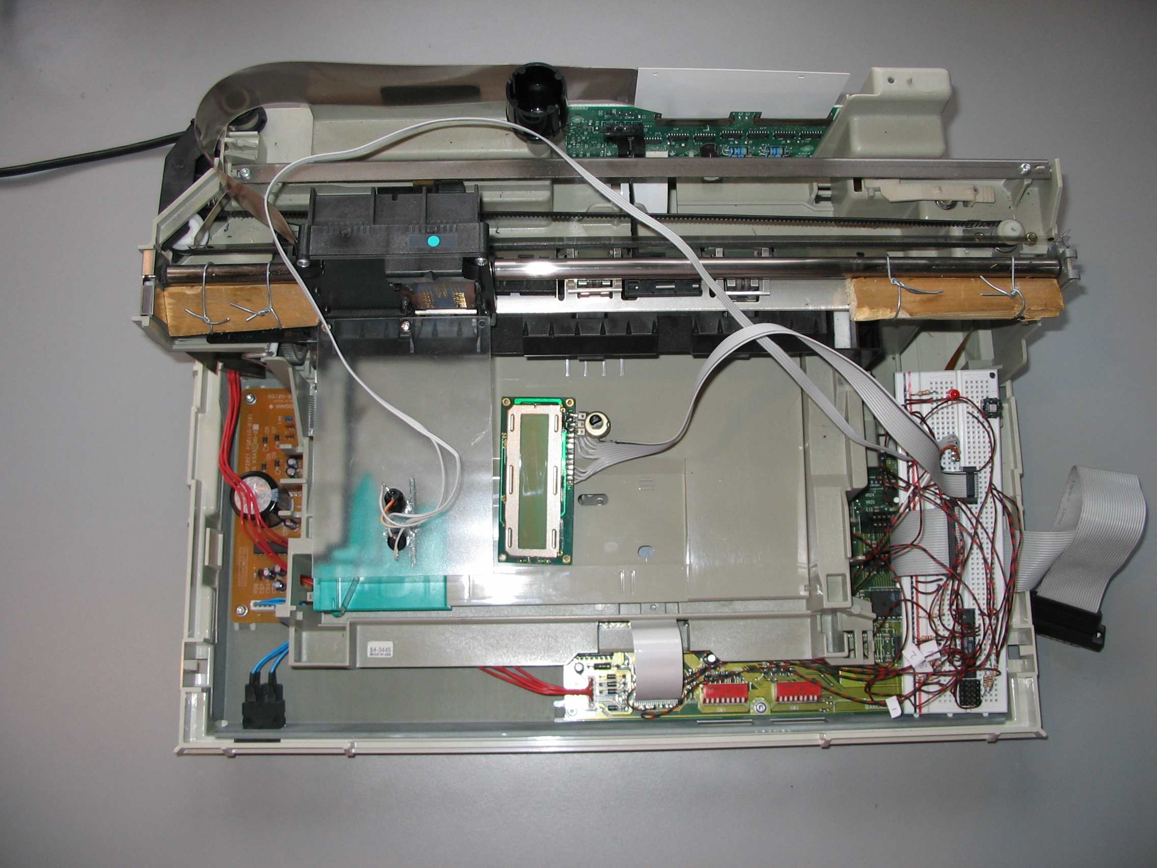
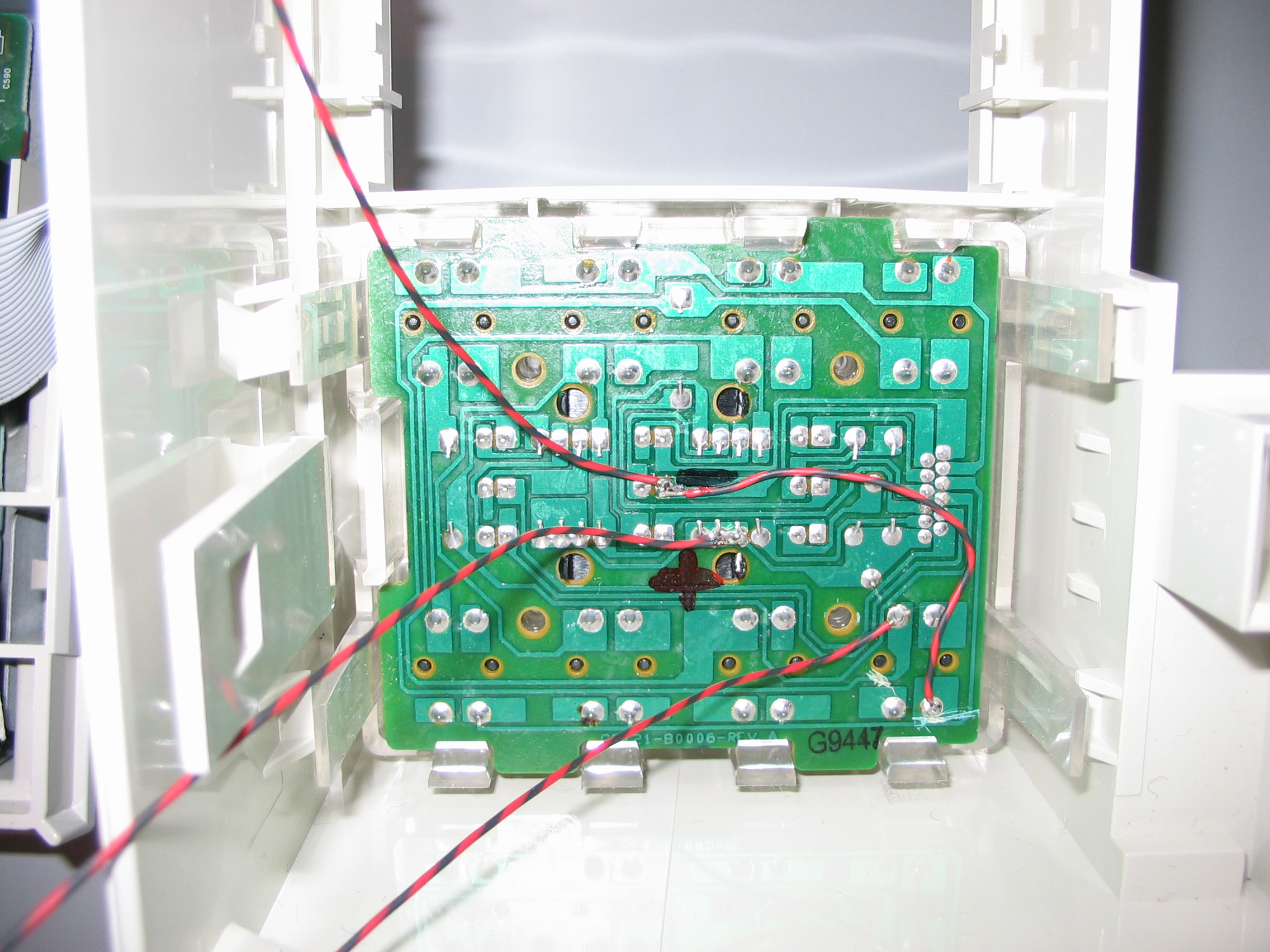
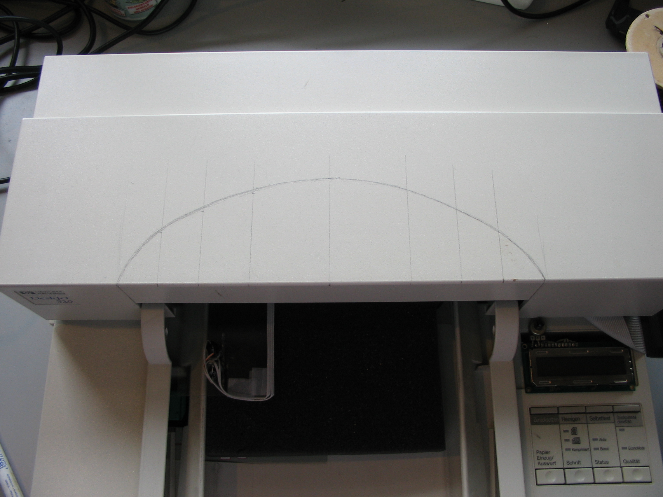
Hidden under plastic cover above the charger plug is a serial port connector. iRobot does not provide support for the serial port, the following quote is from the FAQ section on the iRobot.com website:
Does iRobot provide any codes or specifications for the port?
No, iRobot does not provide this information.
Attempting to alter Roomba’s programming voids the warranty.
Serial Port Specification
The serial port runs at 57600 baud 8N1 with 5 Volt levels. To connect the Roomba port to a PC you have to use a level converter, to convert the 0 and 5 Volt levels of the Roomba port to the approximate -10 and 10 volt levels of the PC port. For level converters see: Simple RS232C Level Converter using Transistors or MAX232 ic.
Serial Connector Pinout
   ___
  |6 7|
 /4   5\
 \1 2 3/
  -- --
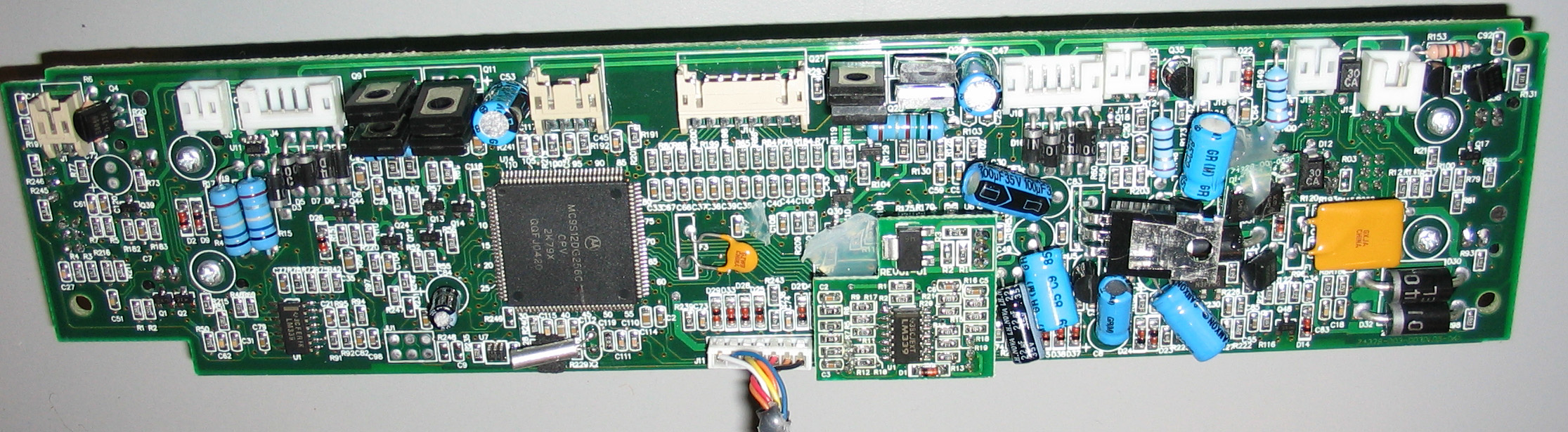
pin1 black – microcontroller pin32 (PH7) via 1K resistor R236, internally pulled up to +5V
pin2 brown – GRD
pin3 red – GRD
pin4 orange – microcontroller pin91 (RXD1) via 1K resistor R239
pin5 yellow – microcontroller pin92 (TXD1) via 1K resistor R238 and 100ohm resistor R243
pin6 blue – battery (+15.6volt)
pin7 white – battery (+15.6volt)
Results
Power Connect
Inserting battery pack displays: ( [^C] is control-C character hex 03 )
bl-start[^C]2004-05-26-1037-L [^C]Roomba by iRobot!
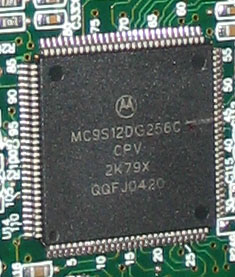
MC9S12DP256
2004-07-30-1026-L
battery-current-quiescent-raw 525 battery-current-zero 511
2004-07-30-1026-L
processor-sleep
Hex dump of reply:
0000:62 6C 2D 73 74 61 72 74 bl-start
0008:03 32 30 30 34 2D 30 35  2004-05
0010:2D 32 36 2D 31 30 33 37 -26-1037
0018:2D 4C 20 20 20 03 52 6F -L    Ro
0020:6F 6D 62 61 20 62 79 20 omba by
0028:69 52 6F 62 6F 74 21 0D iRobot!
0030:0A 4D 43 39 53 31 32 44  MC9S12D
0038:50 32 35 36 0D 0A 32 30 P256  20
0040:30 34 2D 30 37 2D 33 30 04-07-30
0048:2D 31 30 32 36 2D 4C 20 -1026-L
0050:20 20 0D 0A 62 61 74 74     batt
0058:65 72 79 2D 63 75 72 72 ery-curr
0060:65 6E 74 2D 71 75 69 65 ent-quie
0068:73 63 65 6E 74 2D 72 61 scent-ra
0070:77 20 35 32 35 20 20 62 w 525  b
0078:61 74 74 65 72 79 2D 63 attery-c
0080:75 72 72 65 6E 74 2D 7A urrent-z
0088:65 72 6F 20 35 31 31 0D ero 511
0090:0A 0D 0A 32 30 30 34 2D    2004-
0098:30 37 2D 33 30 2D 31 30 07-30-10
00A0:32 36 2D 4C 20 20 20 0D 26-L
00A8:0A 0D 0A 70 72 6F 63 65    proce
00B0:73 73 6F 72 2D 73 6C 65 ssor-sle
00B8:65 70 0D 0A             ep
Power On
Switching power on (turning on green battery led) displays:
key-wakeup
slept for 764 minutes 1091 ticks

2004-07-30-1026-L
battery-current-quiescent-raw 525  battery-current-zero 511
Power Off
Switching power off (turning off green battery led) displays:
processor-sleep
Button Press
Pressing a button on top of the Roomba while power is off displays: (nothing is displayed if power is on)
key-wakeup
slept for 765 minutes 3995 ticks

2004-07-30-1026-L

processor-sleep
Serial Port Pin Input
Grounding pin1 while power is off displays:
key-wakeup
slept for 763 minutes 1841 ticks

2004-07-30-1026-L
device-detect
2004-07-30-1026-L

processor-sleep
Grounding pin1 while power is on displays:
device-detect
2004-07-30-1026-L
Reset via Serial Port
While on, sending control-G resets the roomba as if the battery pack was just inserted:
bl-start[^C]2004-05-26-1037-L   [^C]Roomba by iRobot!
MC9S12DP256
2004-07-30-1026-L
battery-current-quiescent-raw 525  battery-current-zero 511

2004-07-30-1026-L

processor-sleep
Charging the Battery
While the battery is being charged the serial port reports every second the charge time, battery voltage, current and temperature. Below is the part of the serial output where the charger is shut off because of reaching the battery temperature limit.
bat:   min 240  sec 57  mV 16921  mA 572  deg-C 60
bat:   min 240  sec 58  mV 16921  mA 579  deg-C 60
bat:   min 240  sec 59  mV 16921  mA 572  deg-C 60
charging-done: temperature max allowed @ minutes 241
do-charging-wait-for-trickle @ minutes 241
bat:   min 241  sec 0  mV 16866  mA 26  deg-C 60
bat:   min 241  sec 1  mV 16810  mA -27  deg-C 60
bat:   min 241  sec 2  mV 16782  mA -27  deg-C 60
Factory Self Test
Hold down Spot and Clean, then press Power briefly and the LED lights will begin to flash. You can now cycle between the diagnostic modes by using Clean to advance in the sequence, and Spot to return to the diagnostic mode before. For more details see: Roomba Red Diagnostic Mode. Below is the output on the serial port during self test/diagnostics:
factory-test 0  leds
wait: false


factory-test 1  bumpers
(bump-left?) PASS
(bump-right?) PASS


factory-test 2  cliffs-side
wiff: cliff-left on 3627  off 3640  signal 13  on? 0
wiff: cliff-front-left on 3628  off 3633  signal 5  on? 1
wiff: cliff-front-right on 3644  off 3644  signal 0  on? 1
wiff: cliff-right on 3644  off 3644  signal 0  on? 1
wiff: wall on 3652  off 3652  signal 0  on? 0
(cliff-left?) PASS
(cliff-right?) FAIL


factory-test 3  cliffs-front
(cliff-front-left?) FAIL


factory-test 4  wheel-drop-and-wall
(wheel-drop?) FAIL


factory-test 5  rcon-receiver
(rcon?)

factory-test 6  battery-sensors
(battery-voltage-ok?) PASS
(battery-temperature-ok?) PASS
(baseline-current-ok?) mA -92  min -202  max -14  mV 16309  degrees-C 58 PASS


factory-test 7  left-wheel
not left-wheel-stall PASS
(baseline-current-ok?) mA -92  min -202  max -14  mV 16309  degrees-C 58 PASS
(drive-speed-ok? left forward) PASS
(drive-speed-ok? right stopped) PASS
(left-drive-current-ok?) mA -183  min -326  max -118  mV 16253  degrees-C 58 PASS
not left-wheel-stall PASS
wait: left-wheel-stall


factory-test 8  right-wheel
not right-wheel-stall PASS
(baseline-current-ok?) mA -92  min -202  max -14  mV 16281  degrees-C 58 PASS
(drive-speed-ok? left stopped) PASS
(drive-speed-ok? right forward) PASS
(right-drive-current-ok?) mA -183  min -326  max -118  mV 16226  degrees-C 58 PASS
not right-wheel-stall PASS
wait: right-wheel-stall


factory-test 9  wheel-encoders
(drive-speed-ok? left stopped) PASS
(drive-speed-ok? right stopped) PASS
(drive-speed-ok? left reverse) PASS
(drive-speed-ok? right reverse) PASS


factory-test 10  stasis
wait: (not (stasis?))


factory-test 11  main-brush
not brush-motor-stall PASS
(baseline-current-ok?) mA -92  min -202  max -14  mV 16281  degrees-C 58 PASS
(brush-current-ok?) mA -287  min -599  max -241  mV 16226  degrees-C 58 PASS
not brush-motor-stall PASS
wait: brush-motor-stall


factory-test 12  debris
(debris-left?)

factory-test 13  vacuum
not vacuum-motor-stall PASS
(baseline-current-ok?) mA -92  min -202  max -14  mV 16281  degrees-C 58 PASS
not vacuum-motor-stall PASS
(vacuum-current-ok?) mA -7  min -352  max -176  mV 16281  degrees-C 58 FAIL


factory-test 14  side-brush
not side-brush-motor-stall PASS
(baseline-current-ok?) mA -92  min -202  max -14  mV 16281  degrees-C 57 PASS
not side-brush-motor-stall PASS
(side-brush-current-ok?) mA -7  min -248  max -53  mV 16281  degrees-C 57 FAIL


factory-test 15  int-charger-prep
not (int-charger-available?) PASS
wait: (int-charger-available?)


factory-test 16  int-charger-on
wait: (int-charger-available?)


factory-test 17  int-charger-trickle
wait: (int-charger-available?)


factory-test 18  ext-charger-prep
not (ext-charger-available?) PASS
wait: (ext-charger-available?)


factory-test 19  ext-charger-on
wait: (ext-charger-available?)


factory-test 20  ext-charger-trickle
wait: (ext-charger-available?)


factory-test 21  bootloader
(bootloader-ok?) PASS


factory-test 22  complete


SUMMARY: START
SUMMARY: DATE-TAG 2004-07-30-1026-L
SUMMARY: (baseline-current-ok?) PASS   mA -92  min -202  max -14  mV 16281  degrees-C 57
SUMMARY: (left-drive-current-ok?) PASS   mA -183  min -326  max -118  mV 16253  degrees-C 58
SUMMARY: (left-drive-stall-current-ok?) untested
SUMMARY: (right-drive-current-ok?) PASS   mA -183  min -326  max -118  mV 16226  degrees-C 58
SUMMARY: (right-drive-stall-current-ok?) untested
SUMMARY: (brush-current-ok?) PASS   mA -287  min -599  max -241  mV 16226  degrees-C 58
SUMMARY: (brush-stall-current-ok?) untested
SUMMARY: (side-brush-current-ok?) FAIL   mA -7  min -248  max -53  mV 16281  degrees-C 57
SUMMARY: (side-brush-stall-current-ok?) untested
SUMMARY: (vacuum-current-ok?) FAIL   mA -7  min -352  max -176  mV 16281  degrees-C 58
SUMMARY: (vacuum-stall-current-ok?) untested
SUMMARY: (int-charging-current-ok?) untested
SUMMARY: (int-charging-trickle-current-ok?) untested
SUMMARY: (ext-charging-current-ok?) untested
SUMMARY: (ext-charging-trickle-current-ok?) untested
SUMMARY: (bump-left?) PASS
SUMMARY: (bump-right?) PASS
SUMMARY: (cliff-left?) PASS
SUMMARY: (cliff-right?) FAIL
SUMMARY: (cliff-front-left?) FAIL
SUMMARY: (cliff-front-right?) untested
SUMMARY: (wheel-drop?) FAIL
SUMMARY: (wall?) untested
SUMMARY: (rcon?) FAIL
SUMMARY: (any-remote-opcode?) untested
SUMMARY: (battery-voltage-ok?) PASS
SUMMARY: (battery-temperature-ok?) PASS
SUMMARY: left-wheel-stall PASS
SUMMARY: (drive-speed-ok? left forward) PASS
SUMMARY: (drive-speed-ok? right stopped) PASS
SUMMARY: right-wheel-stall PASS
SUMMARY: (drive-speed-ok? right forward) PASS
SUMMARY: (drive-speed-ok? left stopped) PASS
SUMMARY: (drive-speed-ok? left reverse) PASS
SUMMARY: (drive-speed-ok? right reverse) PASS
SUMMARY: (stasis?) untested
SUMMARY: brush-motor-stall PASS
SUMMARY: (debris-left?) FAIL
SUMMARY: (debris-right?) untested
SUMMARY: vacuum-motor-stall PASS
SUMMARY: side-brush-motor-stall PASS
SUMMARY: (int-charger-available?) PASS
SUMMARY: (ext-charger-available?) PASS
SUMMARY: (bootloader-ok?) PASS
SUMMARY: END